
XES02: a laboratory basin, seen as seismic
Two synthetic 3D seismic volumes, one built from dip slices and one from strike slices, derived from a physical sedimentary model and scaled to the size of a real basin. Because the geology is known exactly, they are ideal for testing interpretation, resolution and training.
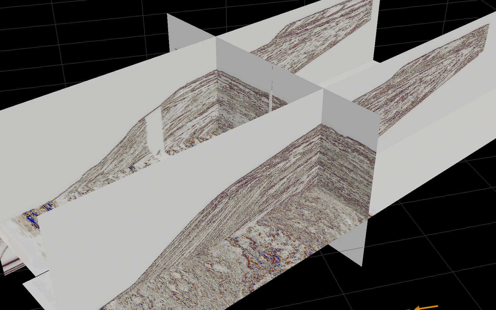
The XES02 experiment
XES02 was run in the Experimental EarthScape (XES) basin at St Anthony Falls Laboratory, University of Minnesota, as part of the National Center for Earth-surface Dynamics research programme. The XES basin is a tank roughly 13 m long, 6.5 m wide and 1 m deep, with a floor of 432 computer-controlled subsidence cells.
The facility lets researchers control sediment supply, water supply, base level and tectonic subsidence independently. XES02 tested the stratigraphic response to slow, fast and superimposed base-level changes under constant subsidence. The result is a fluvial-to-deltaic-to-deep-water deposit with clinoforms, channels and sequence boundaries whose history is fully known.
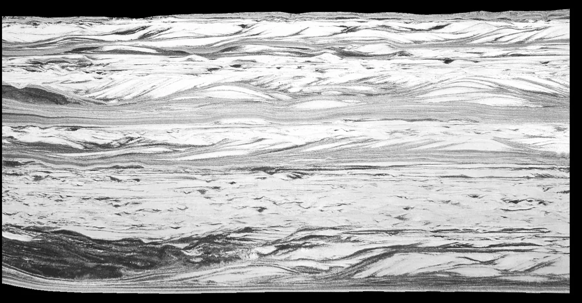
After the experiment, the deposit was saturated with resin and cut lengthwise into two halves. One half was sliced in the dip direction, the other in the strike direction, and every slice was photographed.

From 599 photographs to two 3D seismic volumes
1. Slice images
118 dip slices and 481 strike slices, each 10 mm apart, were scanned at about 200 megapixels. Each pixel represents roughly 0.5 mm of sediment.
2. Classify the pixels
The colour of each pixel reflects its grain size and lithology. We map pixel values to lithology classes, giving a gridded geological model for every slice.
3. Assign rock properties
Each lithology class is given elastic properties (P-velocity, S-velocity and density) and, where needed, fluid properties, to create gridded elastic depth models.
4. Scale to real-world size
The 5.7 m × 3.0 m × 1.4 m deposit is scaled ×20,000 horizontally, to 114 km × 60 km, and ×2,000 vertically, to about 2.8 km depth.
5. Model the seismic response
Synthetic seismic sections are computed from the velocity and density in every cell of every slice.
6. Build 3D volumes
The sections are assembled into two 3D seismic volumes: one from the dip slices and one from the strike slices. Trace spacing is about 10 m along each slice and about 200 m between slices.
The different horizontal and vertical scale factors reduce the laboratory model’s unrealistically steep dips to geologically plausible values.
Dip and strike slices

Known geology, realistic seismic
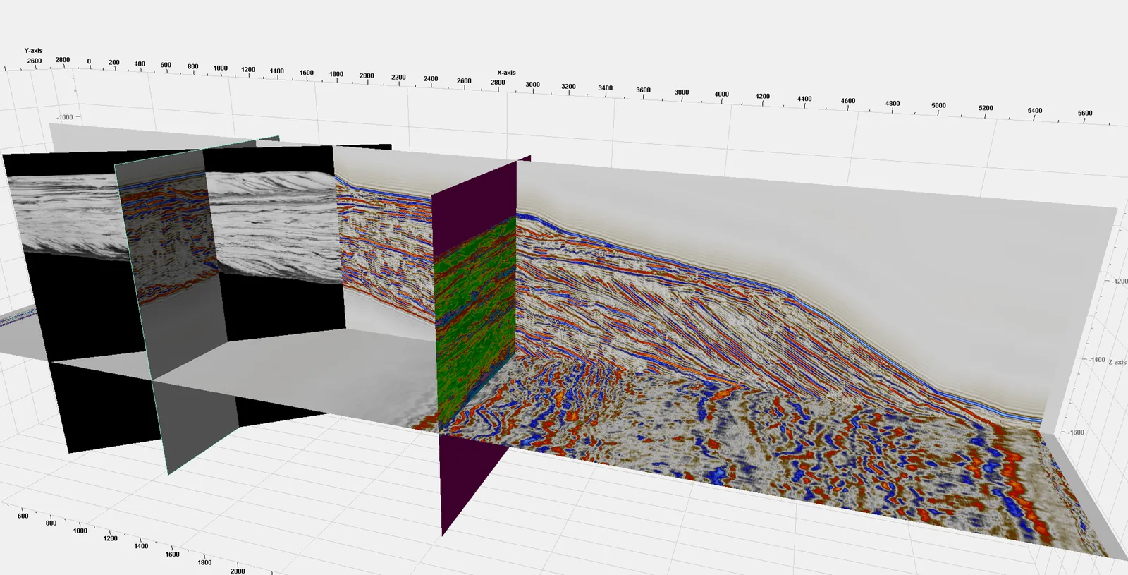
At real-world scale, the XES02 volumes resemble the Taranaki Basin’s transition from the Kapuni coastal plain to deep water beyond Pohokura. The Giant Foresets seen over Maui field are closely replicated.
Because the input geology is known exactly, the datasets let you compare what an interpreter sees in the seismic with what is actually there. Uses include:
- seismic sequence stratigraphy training
- testing how seismic resolution affects interpretation
- screening reservoirs and seals for CCS and gas storage
- benchmarking interpretation, attribute and machine-learning workflows
Built to your specification
The dip and strike synthetic seismic data can be provided at any required spatial dimensions, trace sampling intervals, in TWT or depth, based on user-supplied rock and fluid properties, and in zero-offset or angle-dependent seismic responses. Please contact us to discuss your detailed requirements.
References
- 2026From a 3D tank model to the Taranaki Basin, New Zealand: Understanding controls on sedimentary depositional systems
- 2024Characterising CCS opportunities: Investigating how seismic resolution impacts interpretation of 3D seismic data using a synthetic depositional model
- 2023Characterising CCS Opportunities: Investigating How Seismic Resolution Impacts Interpretation of 3D Seismic Data Using a Synthetic Depositional Model
- 2001Experimental Stratigraphy
- DataXES02 slice images